License : Creative Commons Attribution 4.0 International (CC BY-NC-SA 4.0)
Copyright :
Hervé Frezza-Buet,
CentraleSupelec
Last modified : April 19, 2024 10:22
Link to the source : logic.md
Logic circuit simulator (Labwork)
The problem
The idea is to implement a logic circuit simulator. The (brilliant) solution proposed by Abelson, Sussman and Sussman in their book “Structure and Interpretation of Computer” consists in using wires, and not gates as one would have thought spontaneously, as constitutive elements of the circuits.
A wire is a data item hosting a state (on or off) and a list of actions. An action is a function that is called when the wire changes state. Logic gates, for example, are actions. Indeed, a gate is a calculation that aims to read the state of the input wires, to calculate the state of the output, and then to impose this state on the output wire. An action/gate must therefore be referenced in all the input wires to the gate, because it is indeed the modification of an input that triggers the update of the output wire (which itself can trigger other updates, etc.).
As the same wire can be referenced in several actions, and as an action can be stored in several wires, we will have to manage these multiple references…. hence the idea of using smart pointers.
This labwork thus mixes the use of smart pointers and lambda functions in order to build up in few lines a quite powerfull logic circuit simulation system. What the few lines you will write invokes is quite tricky and clever, so be sure to understand each stage to enjoy it. Fasten your seatbelt.
Methodology
We will only rely on existing classes/structures available in the STL, so we will only define types and functions in order to manimulate things.
Download logic.tar.gz, uncompress it and go inside the directory.
mylogin@mymachine:~$ tar zxvf logic.tar.gz
mylogin@mymachine:~$ rm logic.tar.gz
mylogin@mymachine:~$ cd logic
Here, you will find a gate.hpp file, where you will write the code. All functions are defined in this file, inlined. You will be progressively instructed to write code by making some test-<something>.cpp file compile and execute without error.
Foe example, compiling and executing test test-001-001-display.cpp can be done like this:
mylogin@mymachine:~$ g++ -std=c++17 -pedantic -Wall -I. -o test test-001-001-display.cpp
mylogin@mymachine:~$ ./test
Setting up the basic elements
Display
Our simulator will have to display that some wire change its status (they get in logic state on or off) at a certain time. Let us implement fancy printing functions for this kind of display.
Make test-001-001-display.cpp work by adding the required functions in gate.hpp.
Nota: Formatting text output can be done like this
#include <iostream>
#include <iomanip>  // formatting stuff here

std::cout.precision(2);   // Sets the number of digits after '.' when floats are printed.
std::cout << std::left  << std::setw(10) << "foo";                  // Writes foo******* (* represents a printed space).
std::cout << std::right << std::setw(10) << "foo";                  // Writes *******foo (* represents a printed space).
std::cout << std::right << std::fixed << std::setw(10) << 3.141592; // Writes ******3.14 (* represents a printed space).
Actions
An “action” is a function taking no argument, and returning void. It may seems useless… but indeed, it can be used to store a “frozen” computation, that can be unfrozen (and thus executed) on demand. For example
void f() {std::cout << "Hello" << std::endl;}
Can be viewed as the possibility to say “hello” on the terminal, ready to be used. Saying “hello” is a frozen computation. Unfreezing, i.e. executing, can be done by simply calling f
f();
since this actually prints “Hello”.
Let us use the type std::function<void ()> to handle actions in our simulator. As previously said, for a given action in the simulator may have to be referenced by several things. To enable this, we will rather handle shared pointers on actions, that we will call ref_actions.
So in gate.hpp define the ref_action type like this
using ref_action = std::shared_ptr<std::function<void ()>>;
Make test-001-002-actions.cpp work by adding the required functions in gate.hpp.
Wires
Wires have a boolean state, which is “on” (i.e. true) or “off” (i.e. false). Moreover, the wire hosts a list of actions. When the state of a wire changes (and only in this case), all the actions hosted by the wire have to be executed (once the status is updated).
So a wire is a pair (use the std::pair<A,B> type), containing the boolean representing the status, and the list of actions.
The list do not directly contain ref_action elements, but rather weak pointers. This allows for removing actions and have the wires be able to know that some actions are not available anymore (see the cleaning of weak pointer lists that we have addressed in the smart pointer lectures).
Make test-001-003-wires.cpp work by adding the required functions in gate.hpp.
The simulator backbone: the agenda
The simulation consists of taking, one by one, the instants when the status of a wire changes. The agenda is made of two things. FIrst is a double representing the current time of the simulation, second is an time ordered list of request. A request tells “set this wire to this status”, it is thus a pair made of a wire and a boolean.
Storing an ordered list can be done efficiently with an std::map<key, value>, since it consists of key-value pairs stored in increasing key order. So here, the ordered list of request is a std::multimap<double, std::tuple<ref_wire, bool>>, since we allow for sevral identical keys. So an agenda is a std::tuple<double, std::multimap<double, std::tuple<ref_wire, bool>>>. As we did previously, we will handle a ref_agenda type which is a shared pointer on an agenda.
Based on this, make test-002-001-agenda.cpp work by adding the required functions in gate.hpp.
Do the same with test-002-002-agenda.cpp.
Building up gates
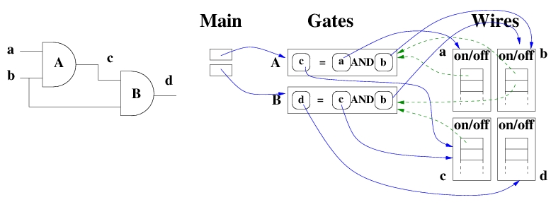
Now, we have the fundations of our logical circuit simulation. Let us design elementary gates. Logic gates are actions, that hold wires to get their status (input) and notify the change of status (output). Wire hold actions, but by a weak pointer. This is done for wires which are used at gate input, so that they trigger the gate action when their status changes.
The following code (do not compile it, it is just a foreword)
int main(int argc, char* argv[]) {
  auto sim = gate::agenda();

  auto a   = gate::wire();
  auto b   = gate::wire();
  auto c   = gate::wire();
  auto d   = gate::wire();

  auto A   = gate::AND(sim, a, b, c);
  auto B   = gate::AND(sim, b, c, d);

  return 0;
}
thus sets up these stuff (shared pointers are in blue, weak pointers are in red).
Probes
Probes are plugged on some wires to display when their status change. The previous test functions have addressed this already, but here, the idea is to provide a convenient tool for that.
Based on this, make test-003-001-probes.cpp work by adding the required functions in gate.hpp.
The AND gate
Let us provide a AND gate in our library. Let us model the duration of the gate computation as a 0.5 second time interval. Make test-003-002-and.cpp work by adding the required functions in gate.hpp.
The OR and NOT gate
Do the same for the a OR and a NOT gate. Use a 0.5 duration for the OR, but only 0.1 duration for the NOT.
Toward integrated circuits
Let us implement a XOR gate. It could be done as previously, since XOR is another binary boolean operator. But here, let us implement the XOR gate as a composition of the basic gates that we already have.
Provide a gate::XOR function, that builds the circuit depicted below.
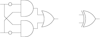
Make test-003-003-xor.cpp work by adding the required functions in gate.hpp.
The adder
Let us use our library in order to implement an adder. We consider now that gate.hpp is ready, it will not be modified anymore. So the adder has to be provided by some adder.hpp file, and tested on your own test file.
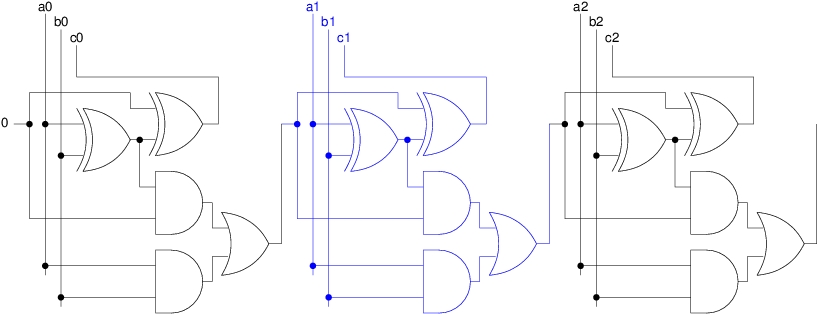
Structure your code as follows. First, implement a 1-bit adder, which is the building block of any n-bit adder. Then, provide a functions that takes the desired number of bits as input, and builds up the corresponding adder.
The figure below shows how a n-bit adder is made of a cascade of 1-but adders (a 1-but adder is highlighted in blue).
Extra tools
You can add in gate.hpp extra tools, for example specific probes that are gathered into an oscilloscope. These probes enable to generate a python file where chronograms are displayed with matplotlib.
Solutions
See logic-solution.tar.gz, but take the time to make your own errors (ask the teachers for some help) before reading this.